
June 2015, OPEN MIND Technologies AG
OPEN MIND CAD Interfaces V10.3
1. General Information
The OPEN MIND Direct Interfaces enable the import of 3D CAD-models in several formats and the conversion into the internal CAD-Format.
Supported CAD platforms and hyperMILL versions
hyperMILL 2013 up to 2015.1
thinkdesign 2009.3, 2011.1 and hyperCAD 2009.3.
Supported Direct Interfaces
The following file types can be converted (depending on the acquired license):
• CATIA V4 (file type:*.model, *.exp, up to version 4.2.4)
• CATIA V5 (file type:*.CATpart, up to version V5-6R2015)
• CATIA V5 (file type:*.CATproduct, up to version V5-6R2015)
• PTC CREO: (file type:*.prt, *.asm, *.xpr, *.xas up to version 3.0 M30)
• Siemens NX (file type:*.prt, up to version NX 9.0)
• Parasolid (file type:*.x_t, x_b, up to version R23)
• SOLIDWORKS up to version 2015
• Autodesk Inventor 2015
Hints to the installation
Condition:
You need Administrator Rights to install the Direct Interfaces. This is also valid for the License server in case of installing network licenses.
Usage with hyperMILL 2013
Please note, that hyperMILL 2013 has to be installed already on your system before installing the CAD- interfaces. Beside this you need new licenses and a Codemeter dongle. For more information on the licensing procedure, please refer to the installation manual that is available on your product DVD.
Procedure
The Direct Interfaces will be provided as a self-extracting exe-file.
After you have downloaded the file OM_CAD_Interfaces_V10_3.exe, please start the installation on your system by double clicking this file. The installation will check, whether there is a supported CAD platform already on the system and will be cancelled, if this is not the case.
The Direct Interfaces will be provided in the following languages: German, English, French, Italian, Korean, Japanese and simplified Chinese. The installation language is depending on the language of the installed CAD program.
Select the corresponding Direct interface out of the list, for which you acquired a license. Please be aware, that the installation will continue only, if at least one module from the list is selected. Now, the installation copies all the necessary files into the corresponding hyperCAD directory of your system.
2. Conversion options
Entity Filter
Using these options, you select the entity types to be converted. When the check-box is activated, all entity types of this category will be converted. Please be aware, in order to get the best result, all categories will be selected by default (exception: Datum planes for PTC CREO).
You can convert Points, Curves, Surfaces, Solids, Axis systems, Texts, Datum planes and Tesselations.
|
|
The entity filter Datum planes is only available for PTC CREO CAD interface. The entity filter Tesselations is only available for CATIA V4/V5 CAD interface. The entity filter Axis systems is only available for PTC CREO and CATIA V4/V5 CAD interface. The entity filter Texts is not available for Parasolid CAD interface. For SolidWorks only the entity filter Surfaces and Solids are available. |
Solid conversion mode
Break down solids into surfaces: Solids are separated into single surfaces. The original topology of the Solid is lost.
Collect solid surfaces into layers: All surfaces will be collected into defined layers (on which shouldn't be other entities). Later, they can be assembled into a solid with a CAD command. Thereby the original layer will be written over.
Collect solid surfaces into components: thinkdesign/hyperCAD entities (solid surfaces) were collected into components during conversion. The name of the elements is used as identification for the generated components. The layer assignment of the solid surfaces remains.
Collect solid surfaces into groups: The original layer assignment is not changed (in hyperCAD-S).
Create solid: All single surfaces persist as part of the solid. The topology of the solid persists. Depending on the settings at the entity conversion mode, a converted solid is composed of NURBS surfaces, cylinder surfaces and planes.
Entity conversion mode
Convert hidden entities: With this option all covered elements are considered during the conversion and converted accordingly.
Create 3D boundaries: The output format (*.e3) contains 3D boundaries that will be available explicitly for further work on the CAD model (e.g. for the contour selection etc...).
Convert all surfaces to NURBS: All analytical surfaces (exception: planes) are converted into NURBS and are available for further usage. If this option is not activated, in this Version (2.3) cylinder surfaces and planes persist as well as cones, bullets and toroids are converted into surfaces of revolution.
Import of CAM features in hyperMILL: CAM relevant Feature of a model is converted to CAM features and is taken over to the hyperMILL feature list. CAM relevant Features are automatically adjusted to the model geometry.
|
|
This Import of CAM features in hyperMILL function is available for CATIA V5 and PTC CREO. |
The settings for File, Tolerance, Layer assignment and Log file you define in the Extended dialog within hyperCAD.
File
Automatic file save: The model is automatically saved with the original model name.
Tolerance
Point tolerance: Two points are recognized as a single point, if they are within the specified tolerance. This is purely a mathematical process that has nothing to do with geometric ‘point’ entities.
Layer assignment
Start layer for surfaces: With this option, you define the start layer for the surfaces that have to be converted. All further surfaces were collected automatically on the next available layer.
|
|
The Start layer for surfaces option is available only if you choose the option Collect solid surfaces into layers before. |
Continue layer count: If you read in more than one model into the same hyperCAD model, the layer count will continue starting with the second one instead of beginning at the defined start layer.
Log file
Same as input file: The log file is saved in the same folder as the input file.
Select path: Choose another path for the log file. In hyperCAD-S choose a path for the log file in the log file path area.
Select file: Define another file name for the log file. In hyperCAD-S choose a file name for the log file in the log file name area.
None: If you choose this option, no log file will be generated.
Show log file after import: If a log file is generated, it will be showed automatically after importing.
Colour mapping
In the More options dialog you define what colours are used when reading in and converting models.
Map colours: When reading in and converting models, the standard colours of the CAD system are used. Thereby in each case a colour is used, that is nearest to the original colour of the model file that is reading in.
Adjust colours: If you choose this option, for Colour range you can define the colours that are changed during reading in in a way, that they meet the original colours. The digits used for Colour range meet those digits, used in the left tab of the hyperCAD dialog Colors and materials (hyperCAD menu Format > Colors and materials).
The selected area is adjusted. Depending on how many colours the model exists of, the colour area should be enlarged. Usually, a standard value of 1-30 should be enough.
Healing
Enable healing: Elements with faults are corrected.
Multiple models:
Available for the Catia V4 and SolidWorks formats.
All models: All models of a file are imported.
Select models: Select the models to be imported.
3.Usage with hyperCAD
Right-mouse click in the toolbar and choose Customize > Toolbars. Activate the desired CAD interface.
Depending on the activated license several icons will be shown in the toolbar.
![]() OPEN MIND Direct
Interfaces: Opens the file selector to
select the CAD files to be converted.
OPEN MIND Direct
Interfaces: Opens the file selector to
select the CAD files to be converted.
![]() OPEN MIND [Direct
Interface] options: Opens the window for controlling the conversion options.
OPEN MIND [Direct
Interface] options: Opens the window for controlling the conversion options.
![]() Axis systems:
Sets the work plane on one of the axis systems
that are read out during conversion.
Axis systems:
Sets the work plane on one of the axis systems
that are read out during conversion.
![]() OPEN MIND Direct
Interfaces Model structure display. Opens the Display structure tree dialog, which shows the model
structure of a CATIA V5 model.
OPEN MIND Direct
Interfaces Model structure display. Opens the Display structure tree dialog, which shows the model
structure of a CATIA V5 model.
Selection of the CAD file
![]() Open the file
selector dialog by clicking the icon.
Open the file
selector dialog by clicking the icon.
Select the file type and the file, you want to convert. Click on the button Open, for loading the file. With the Cancel button you can cancel the loading process.
Converting process
The converting process creates a report (log)-file from, that has the same name like the converted cad-file Ending with "*.log (<CAD-file>.log), located in the same folder.
|
|
Due to there are ambiguous layer assignments in PTC CREO models but no possibility of mapping them in thinkdesign layers, the layer structure of PTC CREO models is not taken over to thinkdesign. |
Set workplane
![]() To set the
workplane on one of the axis systems that is read out during conversion, click
on the icon and select the desired axis system from the list. Note to the name
of the axis system: the original name is the first part of the current term.
To set the
workplane on one of the axis systems that is read out during conversion, click
on the icon and select the desired axis system from the list. Note to the name
of the axis system: the original name is the first part of the current term.
Mapping tables
CATIA V4 mapping table in thinkdesign / hyperCAD (28.06.2004 huv 2. version)
|
CATIA V4 entity |
Type |
hyperCAD / thinkdesign |
Filter |
|
POINT |
1 |
Point |
Point |
|
LINE |
2 |
Line |
Curve |
|
CURVE |
3 |
Spline curve |
Curve |
|
PLANE |
4 |
Plane |
Surface |
|
SURFACE |
5 |
Surface |
Surface |
|
FACE |
6 |
Trimmend surface |
Surface |
|
VOLUME |
7 |
Surfaces |
Surface |
|
3-AXIS SYSTEM |
8 |
ARS (Axis system) |
- |
|
SKIN |
13 |
Surfaces + Component |
Surface |
|
POLYHEDRAL SURFACE |
16 |
Planes |
Surface |
|
POLYHEDRAL SOLID |
17/1 |
Planes/Solid |
Solid |
|
EXACT SOLID |
17/2 |
Surfaces/Solid |
Solid |
|
CIRCLE |
20 |
Arc |
Curve |
|
ELLIPSE |
21 |
Curve |
Curve |
|
PARABOLA |
22 |
Curve |
Curve |
|
HYPERBOLA |
23 |
Curve |
Curve |
|
COMPOSITE CURVE |
24 |
Curves/Lines |
Curve |
|
SPACE DITTO* |
28 |
Entities |
- |
CATIA V5 model structure
![]() To display the
CATIA V5 structure tree, click this icon.
To display the
CATIA V5 structure tree, click this icon.
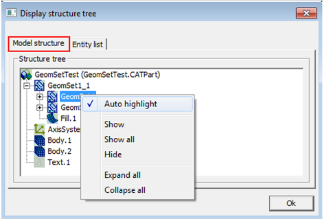
Model structure: All used construction elements are displayed in their original structure. The following functions are available in the context menue:
Auto highlight: the marked element is highlighted displayed in the hyperCAD window.
Show: the marked element is shown in the hyperCAD window.
Show all: the marked element and all its sub elements are shown in the hyperCAD window.
Hide: the marked element is hidden in the hyperCAD window.
Expand all: all elements including their sub elements are shown in the structure tree.
Collapse all: only the main elements are shown in the structure tree.
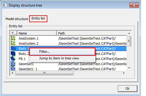
Entity list: All used construction elements are shown as list. The following functions are available in the context menue:
Filter…: Opens the CATIA V5 entity filter.
Jump to item in tree view: the marked element is shown in the structure view.
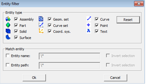
Entity filter
Entity type: all marked entity types are shown in the entity list. All not marked elements are hidden.
Reset: the default settings are restored (all entities are activated).
Match entity: this allows you to filter the view of the displayed entity types by entity name or entity path.
Example: If you enter \*C:\Data\* in the Entity path field, all elements are shown, whose name path contains "C:\Data".
Invert selection: if you enter \*C:\Data\* in the Entity path field and activate the Invert selection option, all elements are shown, whose path name does not contain C:\Data.
New features / bug fixing
Version 9.5
Support of Catia V5R22
Support of SolidWorks 2012
Support of Siemens NX8
Restriction: SolidWorks assemblies of SolidWorks version 2012 are not supported.
CALL number Description
12555 Error when reading CATIA V5 files is fixed.
27294 No more missing surfaces when reading CATIA V5 files.
29532 Trim error when reading CATIA V5 files is fixed.
35907 PTC CREO file can be opened in Feature mode.
36183 PTC CREO files with Features are read correctly (all threads are displayed).
36193 Thread-Features are recognized correctly when reading PTC CREO files.
Version 9.51
CALL number Description
36205 HASP Safenet dongle supported.
Version 9.6
CALL number Description
34848 The problem with reading very large surfaces of SolidWorks is resolved.
35937 SolidWorks 2012 model file can be loaded.
37251 Healing
functionality added to all CAD direct interfaces. It is attempted to bring
surface
boundary curves into line without
changing the surface geometry.
37478 The problem loading a CATIA V5 file is resolved.
Version 9.8
Support of Siemens NX 8.5.
1.3.4 Version 9.81
Support of PTC CREO 2.0 M060.
1.3.4 Version 9.9
Support of Autodesk Inventor 2013 (beta) part *.ipt and assembly *.iam format.
1.3.4 Version 10.0
For CATIA V4 and CATIA V5: Import of
Surface tessellation data.
For Siemens NX: Import von Axes systems and CAD-Features.
Display of the model structure for the formats IGES, STEP and Siemens NX.
Support of Siemens NX9.0 format.
Single holes with threads are in Siemens NX9.0 format are imported.
1.3.4 Version 10.1
Support of Solidworks (file type: *.sldprt) up to version 2014.
Support of Catia V5 R24.
Reading in of an individual Pro/E model with gaps works correct now.
Correct reading in of a model including geometry and features within PTC Creo 2.0.
Lines and contours are completely selected from a NX data set.
Standardization of the layout for the CAD direct interfaces within the hyperCAD menue.
Healing function is set active by default now within hyperCAD.
Version 10.2
Fehlerbehebungen:
No more inaccuracies during Nurbs conversion in SOLIDWORKS format. (SCR BUG_39631)
Trimmfehlerproblem im Format Siemens NX ist gelöst (SCR 46868 und 46869)
Version 10.3
Support of CATIA V5-6R2015
Support of Creo 3.0 M30
Support of SOLIDWORKS 2015
Support of Autodesk Inventor 2015